Documentation
IoDSIM follows the network paradigm initially proposed by Gharibi et al. (2016), being inspired in Cellular networks, the Internet and the Air Traffic Control. In this network environment, drones will fly following well-established airways. Moreover, Zone Service Providers (ZSPs) act as grounded base stations, managing and controlling both airspace and drone communication.
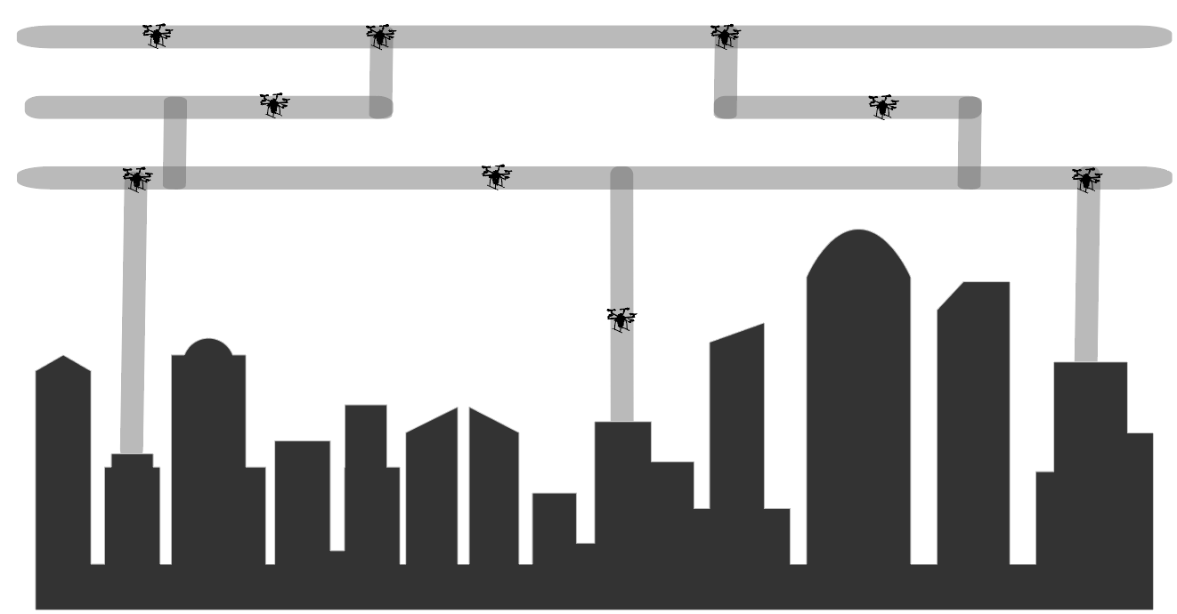
Fig 1. Urban environment with IoD.
Content
To embrace a proper simulation environment for this novel paradigm, IoDSim is organized in different modules, as illustrated by Figure 2. It has two main modules: ZSP and Drone. Both have specific submodules (Drone has mobility module whereas ZSP has Path Planning, for instance) as well integrated ones, namely, Communication and Log.
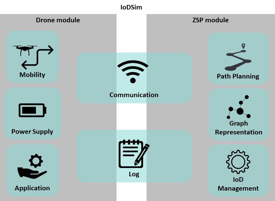
Fig 2. IoDSim modules overview.
This content is grouped in subdirectories, described as follows:
- airway: it contains the classes and modules that support the airway representation;
- application: it contains examples of applications developed as real-world IoD services provided by drones;
- drone: it contains the drone module definitions;
- energy: it contains the base energy module to be associated with a drone;
- log:it contains two base log models, namely, the mobility and energy logs;
- mobility: it contains a base drone mobility model, and a Gauss-Markov based model;
- testcases: it contains some examples of IoD environments built with IoDSim modules;
- utils: it contains scripts that aids in the generation and the analysis of logs;
- xml_examples: it contains some input file examples regarding the airway and path planning specification;
- zsp: it contains the base module that represents zsp as well its base management submodule.
Specific description regarding each OMNeT++ class and files can be found attached into the source code. Mostly of them are based on modules and concepts coming from INET framework. Hence, we strong recomend that you read the INET documentation whenever necessary.
Furthermore, the ZSP module requires two input files to operate: airways and drones path planning specifications. They provide to the ZSP fundamental characteristics to manage the drone's flight, being both specified through an XML format.
Airways XML specification
It aims to represent a "roadmap" of how the aerial space is organized through airways. Based on this specification, the ZSP module creates a graph representation to manage the drones access and flight. The specification has the following tag hierarchy:
- airwaysXML: it indicates the beginning of the environmental airways description;
- limits: it sets the tridimensional environment boundaries, having three attributes:
- x-limit: the environment size related to the X-axis;
- y-limit: the environment size related to the Y-axis;
- z-limit: the environment size related to the Z-axis;
- airways: it contains the set of airways in terms of their fundamental properties:
- airway: it indicates the definitions of an available airspace that a drone can fly. It has as attributes:
- id: the airway unique identifier;
- altitude: the reference altitude (in meters) where the drone will fly;
- boundary: it indicates a radius (in meters) considering the reference altitude that the drone is authorized to fly. Hence, airways delimits a cylindrical region.
- max-speed: the max speed that a drone can fly (in meters per second);
- node: it represents a geographical coordinate (based on x and y-axis) to orientate the drone's flight. It includes a set of achievable nodes (similar to "neighbors") and a set of airways that the node is related. In a nutshell, it is similar to checkpoints, having as attributes:
- id: the node unique identifier;
- x: the x-axis coordinate;
- y: the y-axis coordinate;
- intersection: a boolean value to indicate if this node represents an intersection point, according to the definition of Gharibi et al. (2016);
- nodes-to-go: it contains a set of achievable nodes that a drone can go where it is flight over the current node:
- node: it represents the achievable node where an ID need to be passed as attribute, linking it with an existant described node;
- airways: it contains a set of airways that the current node is related. Thus, this set indicates paralell z-axis coordinates of the current node:
- airway: it represents an already described airway, indicated by an ID attribute.
Path Planning XML specification
It aims to describe a path planning for a set of drones. It is mandatory that all path plannings correspond to the airspace described in an airway XML input file. Based on this specification, the ZSP will generate and store the path planning for each drone, sending it to the corresponding one according to the ZSP management module. The specification has the following tag hierarchy:
- path-planning: it represents the major tag embracing the path plannings description;
- drone: it refers to the drone whose path plannings will be linked. It has an unique identifier id as attribute;
- trips: it contains a set of trips for the parent drone. As attribute, it can have a simulation start time, denoted by start, that will indicate when the first trip will begin;
- trip: it indicates a trip that the drone will fly. It has as attributes:
- id: the unique trip identifier;
- airway: it carries the airway ID that the trip will be performed. It must be in accordance with the airways specification;
- full: it is a boolean attribute that indicates if the trip is described considering all the nodes to fly, or if the description contains only the initial and the ending point. In this latter, the ZSP management module will process the "intermediary" nodes of the trip through a given metric, for instance, the minimum path;
- node: it denotes a node that the drone need to achieve in the flight. The sequence of describe nodes composes the trip.
To keep both specifications concise, it is necessary to be aware of the following constraints:
- The x and y values of a node must attend the x-limit and y-limit, respectively;
- All nodes specified in nodes-to-go lists must have a corresponding ID in the general description of nodes;
- All drone IDs specified in path planning XML file must have a corresponding one in the carried simulation;
- Given two subsequent trips t1 and t2 (excepet when t2 is the last trip), the last node of t1 must be the same as the first node of t2, indicating a trip continuity.